OLED SSD1306 Examples
Using the SSD1306 with I2C Interfaces
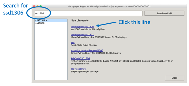
Add the ssd1306 Python Module
You can now use the Thonny "Tools -> Manage Packages..." menu to add the Python driver for the SSD1306 device. You will need to do this for every new device you use.
If the Manage Packages menu is disabled, then you will need to go into the shell and add it with the pip command.
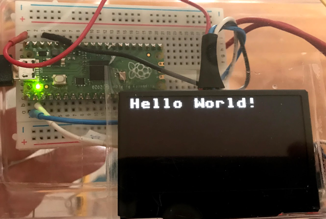
I2C Hello World
1 2 3 4 5 6 7 8 9 10 11 | |
After this program runs you should see the text on your OLED display.
SH1106 Example
1 2 3 4 5 6 7 8 9 10 11 12 13 14 15 | |
Counter Example
In this example we will updated the display 50 times with a 1/10th of a second pause between each refresh. A counter will cycle from 1 to 50.
1 2 3 4 5 6 7 8 9 10 11 12 13 14 15 16 17 | |
Animated Box
This draws a title and four lines around a drawing area. It then draws boxes that move to the right.
1 2 3 4 5 6 7 8 9 10 11 12 13 14 15 16 17 18 19 20 21 22 23 24 25 26 27 28 29 30 31 32 | |
Install SSD1306 Module
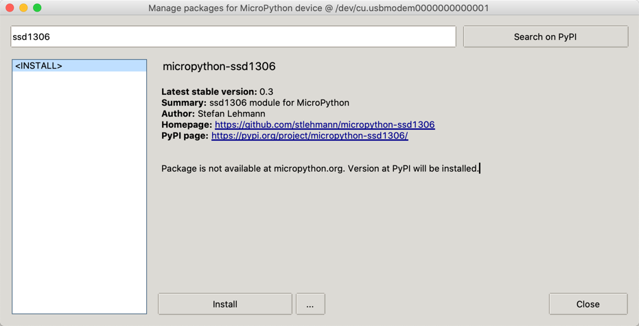
ssd1306 module
SSD1306 Library - click the RAW button and then right click to do a "Save As"
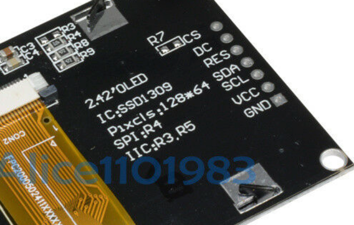
SSD1306 vs. SH1106
There is only one small difference between SSD1306 and SH1106: The SH1106 controller has an internal RAM of 132x64 pixel. The SSD1306 only has 128x64 pixel.
The SPI interface
The four wire I2C interface is great for kids that don't want to hook up more than four wires. But there are times when we want a higher performance screen with faster refresh times. This is when the SPI interface comes in handy.
SPI Baudrate
https://raspberrypi.github.io/pico-sdk-doxygen/group__hardware__spi.html#ga37f4c04ce4165ac8c129226336a0b66c
The seven wires on the back of the SPI OLED screens are the following as read from the top to bottom looking at the back of the display:
- CS - Chip Select - pin 4
- DC - Data/Command - pin 5
- RES - Reset - pin 6
- SDA - Data - SPIO TX GP7 pin 10
- SCL - Clock - Connect to SPIO SCK GP6 pin 9
- VCC - Connect to the 3.3V Out pin 36
- GND - pin 38 or 3 any other GND pin
Pico Pins
1 2 3 4 5 6 7 8 9 10 | |
SCK is the clock - hook this to the oled SCL MOSI is the line taking data from your Pico to the peripheral device. Hook this to SDA
From the SDK: https://datasheets.raspberrypi.org/pico/raspberry-pi-pico-python-sdk.pdf Section 3.7
- SPI0_SCK - pin 6
- SPI0_MOSI - pin 7
- SPI0_MISO - pin 8
This contradicts p122 in GET STARTED WITH MICROPYTHON ON RASPBERRY PI PICO
1 2 3 | |
SPI Terms
Master Out Slave In (MOSI)
We send the data to the SPI RX (Receive) port on the Pico. These are pin 1 (GP0) or pin 6 (GP4)
Sample Nonworking SPI Code
From the documentation:
From
spi is an SPI object, which has to be created beforehand and tells the ports for SCLJ and MOSI. MISO is not used.
dc is the GPIO Pin object for the Data/Command selection. It will be initialized by the driver.
res is the GPIO Pin object for the reset connection. It will be initialized by the driver. If it is not needed, it can be set to None or omitted. In this case the default value of None applies.
cs is the GPIO Pin object for the CS connection. It will be initialized by the driver. If it is not needed, it can be set to None or omitted. In this case the default value of None applies.
1 2 3 4 5 6 7 8 9 10 11 12 13 14 15 16 17 18 19 20 21 22 23 24 25 26 27 28 29 30 31 32 33 34 35 36 37 | |
References
DIY More OLED Product Description
- Using I2C Defaults